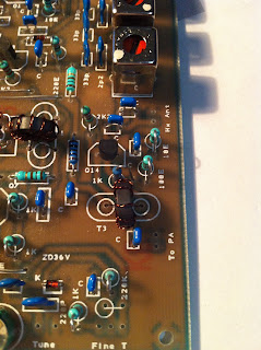
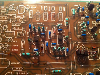
I had to make this a separate blog post.....
but the exciter is finally done....
Here it is :)
Now on to the PA part... yeah more coils :|
HAM, Antenna, tranceivers, coax cable, PD0SBM, PA1SBM, Veron, VRZA, Kenwood, Diamond, Comet, Falcon,
Saturday, April 14, 2012
BITX20 - 13. The output driver
The output driver section was not hard.... even with the coil to be wound...
It was a bifilar, not a trifilar.... so that made it slightly less annoying :)
as this is near the end, i now noticed i am missing a few more things....missing a 100 Ohm and a 1k Ohm resistor. No Clue what i am gonna miss next :)
This for me is one of the charming things of the Indian package. Now if i paid the qrpkits.com price, i would probably mail them for every single item i missed. Now i just took them from my own stock.
As you can see... it is just a small part...
Measurments came out fine, so no worries there!
Friday, April 13, 2012
BITX20 - 12. Xtal section...
Ok , this was hardly any work.... 4 xtal's and 3 capacitors....
No measuring either....
Now there is only 1 section left on the exciter... the output driver.... with a dreaded trifilar coil @#$@#
No time left now to make it. maybe late tonight....
No measuring either....
Now there is only 1 section left on the exciter... the output driver.... with a dreaded trifilar coil @#$@#
No time left now to make it. maybe late tonight....
BITX20 - 11. Audio section completed
This was easy until i noticed that i was missing some parts.... I missed a 1uF capacitor, and i noticed i had a 10uF in my capacitors bag. I have done some reading in the part lists in the manual , but i think thy misplaced a 1 by a 10 uf capacitor... As any DIY person should, i took a 1uF from my own stock, and put it in.
The same happened for a .001 uF capacitor... again ... $100 including shipment... i am not complaining.
The only thing weird is that my Q10 measurements are a bit too much off for my liking so i will check those with PA1ED (yes he got his full license now!) and see what his measured value's were.
As they are not way off, I'll continue for now.
On to the XTAL section !
Edit:
Note:
For those who wonder why i now all of a sudden build a lot compared to the usual slow pace....
I treated myself to a few days off... :)
BITX20 - 10. BFO / Modulation section done.
ARRGHHH i was tricked.... well i just did not read stuff good enough...
There were 2 coils... one not that bad, but the other was the 3rd dreaded trifilar coil....
And i know that for the exciter board i still have to make one. (and 2 i believe for the PA)
Anyway , the rest of the build was fast and painless.... (except for the manual saying 50uF, and them supplying 47uF) (also a normal fitting potentio meter would have been nice)
So lets not complain :)
Measuring all showed me no weird things... Just the normal difference... measurments just never seem to be exact :)
Audio section is next.... And now i checked the list... no coils :)
Thursday, April 12, 2012
BITX20 - 9. Building and meassuring the 2nd IF Amplifier
Oh how much joy building none coil parts :)......
So the 2nd IP Amplifier was done in no time..... and i enjoyed it a lot!
Does any1 notice the 1 resistor being a different color ????
Yes indeed , 1 resistor was not included in the complete package. a 4.7 Ohm resistor.
Luckily i had one in stock.
Measuring this part was fun as well.....
There is a Q3 and a Q3a transistor.... and in the manual they have mixed up the value's what you should measure. So this again is one of the quirks from the BITX20 kit.
So if it says Q3, read Q3a , and if it says Q3a, read Q3..... And remember that this is a $100 kit :)
On to the next part !!! (still has no coils ;) )
BITX20 - 8. Building the 1st IF amplifier
After finally having done the trifilar coils, i felt like building more :).
So i builded the 1st IF Amp as well last night. It's all very straight forward.
I do not expect any problems here. This is how it looks......
Again you can see that the transistors are "the wrong way around" to the masking on the print itself....
This is still due to the change of transistor type Sunil has put in his kits. From what i have read on his blog, the new v3 kits should have a proper masking again, but i am not sure.
I intend to do all the measuring after i get myself another cup of tea.... Luckily the whole test setup from last night is still on my desk , so i can start straight away. I do not expect anything weird here so probably the next post will be on building the post if part....
BITX20 - 7. Building and measuring the "First Mixer"
This is by far the most dreaded part for me.... I don't know why, but i just do not like to wind coils.....
So that is the reason i have been putting it off for so long.... But! i forced myself to do it and.....
TAADAAA!!!!
There are the 1st two trifilar coils. Thank god that was done. Putting in the 4 1n4148 diodes was easy , so now this very small section looks like this....
After this we finally could measure voltages on the last transistor of the vfo part, and that turned out fine.
On to the next part !!!
Subscribe to:
Comments (Atom)


