And all of a sudden I stumbled on an advert with a PCB+components for a mini-whip....
Now, as I wanted to build one for a while, but did not feel like going through the trouble building my own PCB's, so I ordered a kit at this webshop....
It's a very simple and basic kit.... So out came the components and the soldering iron was turned on....
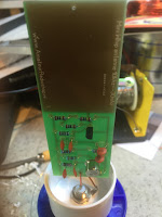
The PCB's are very nice... BUT!, i was taught that you should never use 90 degree corners, but use 2 of 45 degrees instead. I was told that it is wise to keep the actual antenna part as close to the gate of the J310. and although it is close, i can see some small improvements in the layout of the PCB.
But, don't get me wrong, it's a very nice PCB!
So after a few minutes......
There are not that many components so it did not take me too long....
One thing to remember is that the PSU PCB needs to be soldered on 2 sides!
Hopefully you can see the soldering of the C's on the upper layer of the PCB....
So all was left was to put all in a housing and start to test this antenna.....
I found a very nice housing for the PSU at a fair.....
So I hooked everything up and started to test the reception of the Mini-Whip....
I made a short video of some CW i found on 40m. There was not much going on on other bands...
Propagation was bad, and the time i was listening was not that great either.....
Ant1 is the Falcon out-250b (outside) and Ant2 is the Mini-Whip behind a double window, inside , close to my switching power supplies...... Not the best place :)
So my conclusion was..... I am amazed.... Yes the base noise level is a bit higher, but the signal is as good as my outside antenna! And the mini-whip is not at a good spot at all....
The mini-whip will go outside somewhere away from the house. which probably will be good for the noise level.


No comments:
Post a Comment